 MagSim
MagSim Knowledge · Toroid Core Basics Beta
Toroid Core Winding Design
Working out a target turn count electrically only takes a formula. Whether it actually fits mechanically into the core – with the chosen wire, insulation gaps and tool clearance included – is the real challenge. This article shows what matters and how MagSim works out the winding live for you.
Electrical target first, then the mechanical check
The starting point is usually a desired inductance. The core's AL value quickly gives you a turn count from that – see Toroid Core AL Value Calculation: N = √(L / AL). That formula knows nothing about wire diameter or window size, though. Whether the resulting turn count actually fits into the core with a real wire is a second, independent check – and that's exactly what this article covers.
The rough estimate – and why it's usually too pessimistic
The obvious first approach: divide the window circumference by the wire's outer diameter, i.e. assume a single layer along the window edge.
Nrough ≈ π · 2·Rw / dwire
Window radius Rw = 13 mm, enamelled copper wire 0.50 mm (outer diameter incl. enamel 0.545 mm):
Nrough ≈ π · 26 mm / 0.545 mm ≈ 150 turns
This estimate clearly underestimates the real capacity, because it only uses the window's edge, not its whole area. Turns can also be packed radially inward in multiple, honeycomb-nested layers – much like stacking spheres. For the same window, MagSim's hexagonal-lattice model works out 636 actually possible turns in this example – roughly four times the rough estimate.
What further reduces the usable winding space
The raw window area is only the starting point. In practice, less of it remains usable than the bare core dimensions suggest:
- Fill factor kwDetermines how tightly the next layer moves in radially – not how many gaps are deliberately left open within a layer. How tight that gets depends on skill or the winding machine, not on a fixed value.
- Pull hookThe pull hook guides the wire through the core opening – an area at the window centre must be kept free for it from the outset, with no turn reaching into it.
- Insulation gapWith more than one winding (M ≥ 2), a continuous corridor must remain free between the windings so their wires never touch.
- HousingAn optional housing lines the core bore from the inside (protecting against the core's sharp edge) and further shrinks the usable window.
How MagSim handles this for you
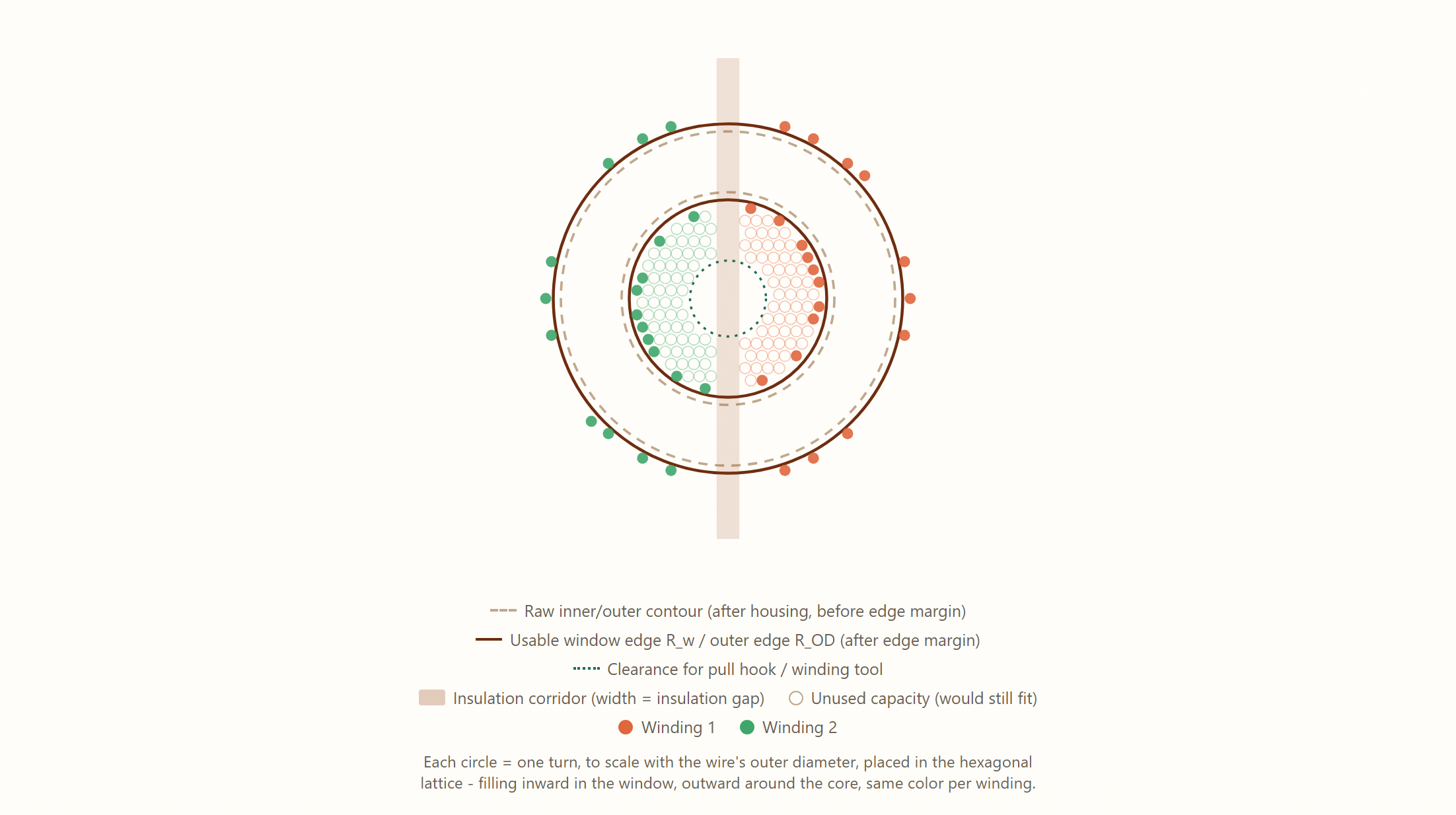
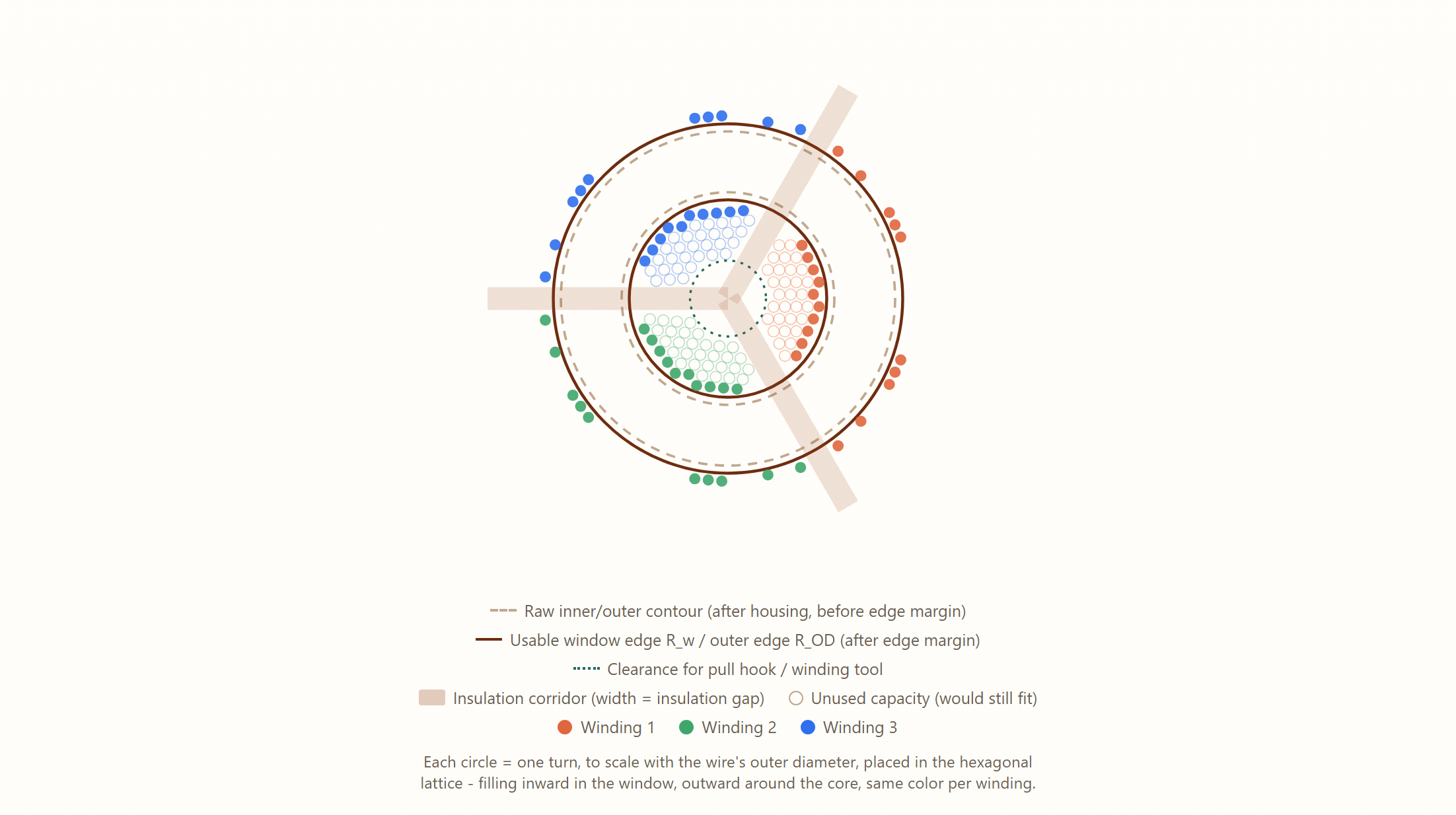
Both examples below deliberately use a thicker wire than in the worked example above – so individual turns, the pull-hook clearance and the insulation corridor stay clearly visible instead of disappearing into a dense hexagonal pattern.
Live, not by hand
Instead of working out window area, wire diameter and fill factor by hand, MagSim checks live in the generator whether a desired turn count fits mechanically with the chosen wire – including a traffic-light readout (fits well / tight, just fits / doesn't fit), figures like copper weight and wire length per winding, and the to-scale winding diagram shown above. The wire data itself comes from a built-in wire library instead of a separately looked-up datasheet. The number of windings (M) can be picked directly as 1, 2, 3, or a custom value.
This feature is marked Beta: currently available for round cores only, and calculation and rendering may still change. A full electrical design (saturation, AC losses, dielectric strength) is deliberately not part of this first stage.
What multiple windings (M) are actually for
- M = 1 – single winding, e.g. a storage inductor or simple filter choke
- M = 2 – center tap for symmetric circuit stages
- M = 2, bifilar – common-mode choke for noise suppression on signal/data lines
- M = 3 – e.g. a three-phase common-mode choke
With M ≥ 2, MagSim places each winding in its own sector of the window, separated by the insulation corridor described above – visible in the diagram by the different color per winding.
On choosing wire
The "enamelled copper wire" family built into MagSim follows common dimension tables from the IEC 60317 standard series. Custom, customer-specific wire values can also be entered freely if a particular datasheet differs from the built-in reference values.
Design your own wound toroid core now (Beta)
Choose core geometry and wire – MagSim checks live whether the desired turn count fits mechanically, and shows copper weight, wire length and the winding diagram right away.
Register for freeFrequently asked questions
How many turns fit on a toroid core?
There is no fixed number – it depends on the core's window area, the wire's outer diameter (including insulation), the fill factor kw, and the clearance needed for the pull hook and edge margins. MagSim calculates the turns that actually fit live from these values, instead of estimating roughly.
What does the fill factor kw mean when winding?
kw does not describe how many gaps are deliberately left open within a layer, but how tightly the next layer moves in radially. How tight that gets in practice depends heavily on the winder or the winding machine, not on a blanket figure.
Is the winding feature in MagSim already fully usable?
The mechanical sizing (does a turn count fit in the window with a chosen wire) is production-ready, but marked as beta: currently round cores only, without a full electrical design (saturation, AC losses). Calculation and rendering keep evolving based on feedback.