 MagSim
1. Create an account and confirm it
Registration happens at /register with an email address and password. MagSim then sends a confirmation email with a verification link that stays valid for 24 hours. The account only becomes usable once you click that link.
If the link has expired, simply register again with the same email address – MagSim automatically sends a fresh confirmation link.
2. Know your limits as a free user
MagSim is a private, self-funded project. Anyone who registers gets the external_user role, which comes with three limits meant to be transparent from the start rather than a later surprise:
- 3 designsGlobal limit on simultaneously active, saved designs (default value – admins can adjust it case by case). Deactivated designs don't count toward it.
- 10 / dayDefault daily limit on generations. Configuring and experimenting in the generator itself doesn't count – only clicking "Generate" does.
- STEP + PDFExport formats for external users. The raw, fully editable CAD project file (FCStd) is reserved for internal users and admins.
3. Your first design in the generator
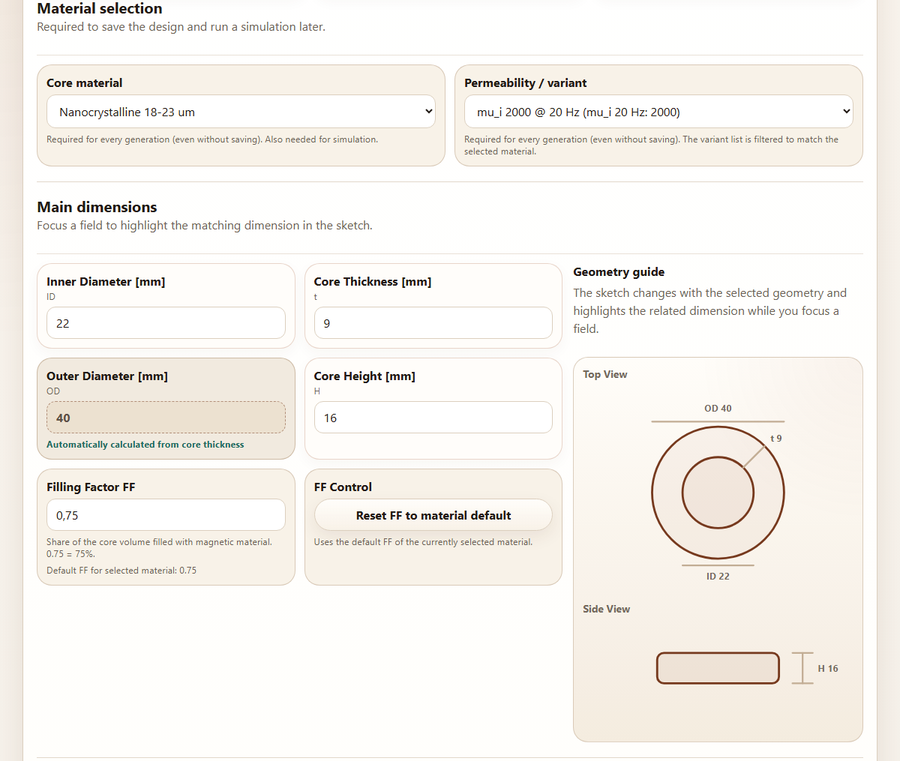

The generator at / is the central starting point. Two decisions come first: the geometry (round, rectangular or triangular) and the mode – simple mode only needs inner diameter, core thickness and height, with outer dimensions calculated automatically; advanced mode makes every dimension directly editable.
Core material and permeability variant are required fields for every generation – even without saving – because they feed into both the drawing and the simulation. The sketch on the right adapts automatically and highlights the matching dimension in color whenever you focus a field.
Additional build-up (optional)
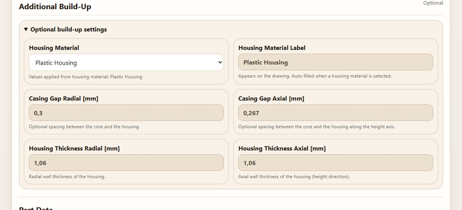
This section is more than a note – housing material, casing gap and housing thickness are actually added to the CAD model and the drawing as an extra body. Worth using once the core isn't installed bare, but housed or potted, and you want to see or dimension that in the model and drawing.
- Housing materialSelecting one from the housing material database (e.g. Plastic Housing, Epoxy) automatically calculates the four values below from outer size and height. "Custom" leaves all four values freely editable.
- Casing gapOptional air gap between the core and the housing, configurable separately for radial and axial.
- Housing thicknessWall thickness of the housing, configurable separately for radial and axial.
Leaving the section empty produces a model without a housing – the default case, and usually sufficient for pure core sizing.
Part data (optional)
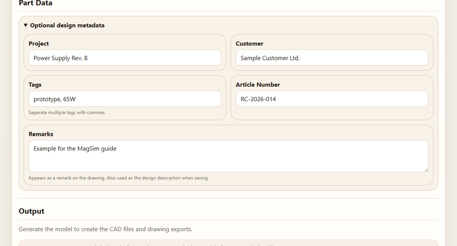
These five fields serve two different purposes – worth knowing so the right information ends up in the right place:
- Article number, remarksAppear directly in the title block, or as a remark, on the generated drawing – visible to anyone who opens the PDF.
- Project, customer, tagsPure organizational metadata for your own design library. They don't appear on the drawing, but serve as filters there later (see section 5).
4. Understanding the result
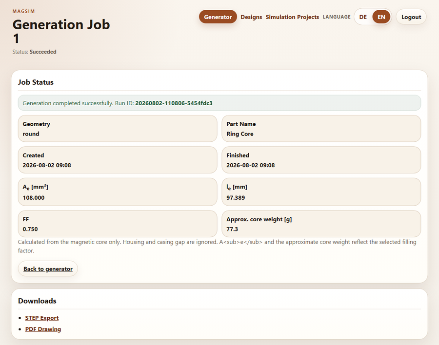
After clicking "Generate", MagSim takes you to a job status page. While the job is running, the page refreshes itself automatically; after a few seconds it shows the status "Succeeded" together with the derived magnetic characteristics – effective cross-sectional area Ae, effective path length le, filling factor and approximate core weight.
Below that is the Downloads section with the finished export files, ready to click: STEP Export is the CAD file for further processing in any common CAD program, PDF Drawing is the technical drawing. Generated files are automatically cleaned up after a few hours – but the job and its characteristics stay visible in your account indefinitely, and generating again from the same design simply recreates them on demand.
Two pages in one PDF
The technical drawing is always a genuine two-page DIN A4 drawing – generated in English regardless of the UI language, so it can be handed to manufacturers without translation. Page 1 shows the dimensioned construction including the title block, page 2 the simulated AL and impedance curves with a tolerance band. See the article on the technical drawing for details.
5. Saving and finding designs again
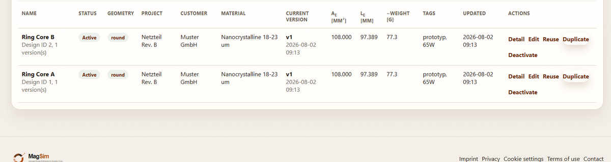
A design name in the "Design Workflow" field plus "Save design" creates the design as version 1 in your account. From there, two paths lead back: in the design library you can reuse a design directly (generate it again unchanged) or load it in the generator (as a starting point for changes). If you're not signed in when you click, the link takes you to sign-in first and then automatically back to the library.
Important: editing never overwrites the previous state. Every change creates a new, immutable version – the full history is preserved. For a completely new variant based on an existing design, "Duplicate" is the right tool instead.
6. Comparing multiple designs
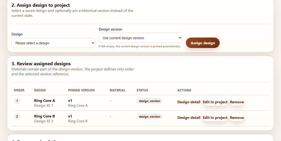

To compare several designs side by side, create a simulation project. In the "Assign design to project" section, pick a saved design from the list and confirm with "Assign design" – optionally pinning a historical version instead of the current one. The table below shows at a glance which designs are currently assigned, including the pinned version and a "Remove" action per row.
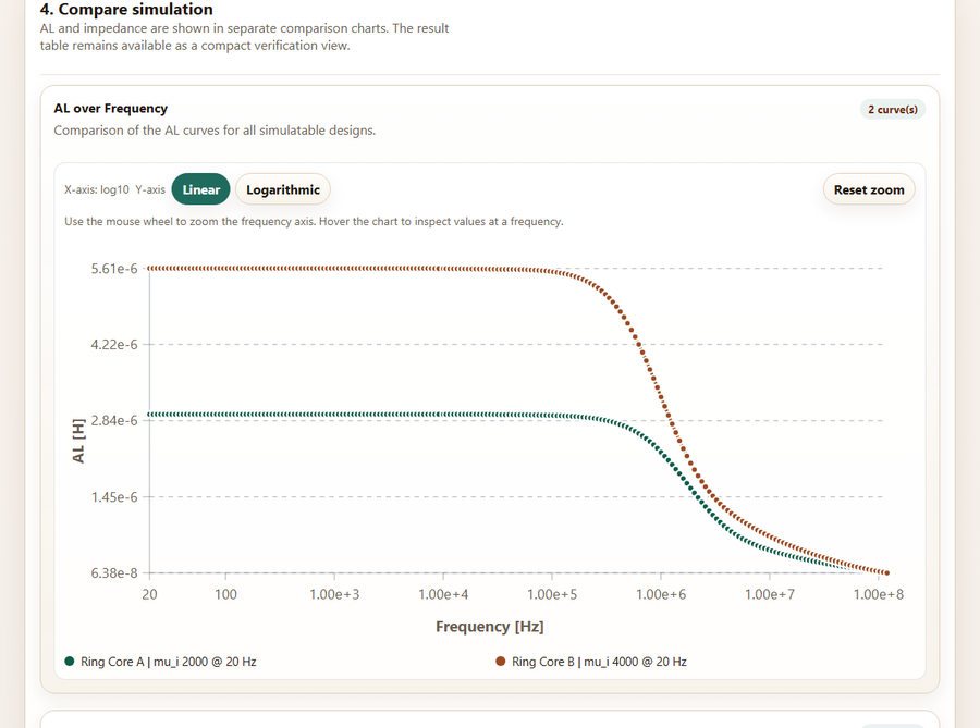
Once at least one design is assigned, the comparison charts appear below: AL and impedance curves for all assigned designs in the same chart, color-coded and named in the legend – with hover values, zoom on the frequency axis, and a switchable linear/logarithmic Y-axis.
Three tips for effective use
- Set the filling factor deliberately instead of keeping the default
- Duplicate instead of rebuilding for variants
- Click a dimension instead of searching the sketch
The filling factor FF (default 0.75) directly affects Ae and therefore the AL value and impedance – a realistic, material-specific value pays off more than the blanket default. For a new variant of an existing design, "Duplicate" is faster and less error-prone than re-entering everything from scratch. And: clicking into a dimension field automatically highlights the matching dimension in the geometry sketch – useful for keeping track on rectangular or triangular cores.
Get started now
Register for free, confirm your account, generate your first design – no installation, straight in the browser.
Register for freeFrequently asked questions
Do I need CAD or electrical engineering experience to use MagSim?
No. Geometry and material are entered through form fields with hint text and a live sketch – MagSim handles the magnetic calculation and CAD/drawing generation automatically.
What happens when I reach my design limit?
New designs can only be saved again once an existing one is deactivated, or an admin raises your personal limit. Generating and downloading without saving remains possible regardless.
Why don't I get an FCStd file as an external user?
FCStd is the fully editable FreeCAD source file. External users receive STEP (for further CAD processing) and PDF (drawing) – covering the typical use case without exposing the full project file.